Image ?: Main parts of yagi antenna.
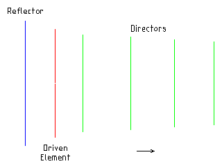
A Yagi-Uda (Yagi) antenna is a directional antenna which is made up of of a dipole element with a reflector and one or more director elements.
The Driven Element is a dipole which consists of two 1/4 wavelength elements. The Reflector is slightly bigger then the driven element and reflects the signal back towards the driven element. The Directors are slightly smaller then the driven element with each one being slightly smaller again as they move away from the driven element, the directors help to focus the signal giving it a higher gain. The main gain is directed in the same direction as the arrow.
The design of a yagi antenna is much more complex and requires a lot more experimentation then a monopole antenna. I don't believe there is any known simple mathematical formula that can be used to design a yagi antenna. Am I correct?
What we do have is a rule of thumb which gives a start pointing when designing a yagi antenna. The idea is to scale up the reflector element by about 5% over the driven element, and to scale down the first director elements by about 5%, and to scale down again by about 5% for each extra director. The spacing between each of the elements would be about 20% of a wavelength, these can also be scaled down for each director.
Using this starting point you can adjusted each of the elements lengths and there offsets until you find the best preforming design. These adjustments can be easily and quickly made using antenna design software.
The result of a number of days of tweaking lengths and offsets can be found in the following nec file, gsm-900_6element_yagi.nec. I also have other nec files for the different gsm bands, gsm-550_6element_yagi.nec, gsm-1800_6element_yagi.nec and gsm-1900_6element_yagi.nec.
The animated image shows the radiation pattern of the antenna, the gain varies from just under 9 dB to over 10 dB over the frequency range 876 MHz to 960 MHz, covering the three main GSM-900 bands. The design also shows good VSWR (Voltage standing wave ratio) and F/B (Front to back) Ratio.
Some other useful sites with information on yagi design include, W4RNL - Antenna Articles, GM3SEK - VHF/UHF Long Yagi Workshop and K7MEM - VHF/UHF Yagi Antenna Design (design software written in JavaScript).
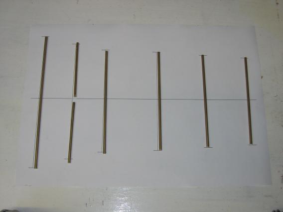
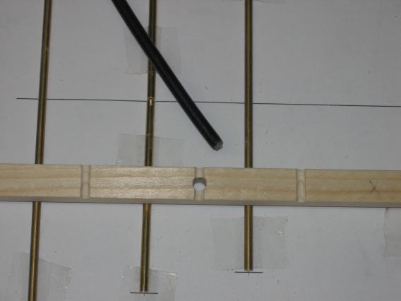
There is room for flexibility in the construction techniques you can use. I experimented with different options for the beam including, drilling holes for the elements in wood and plastic (I was disappointed with the accuracy), using a custom printed circuit board (this worked for the prototype but would not be suitable for others to build).
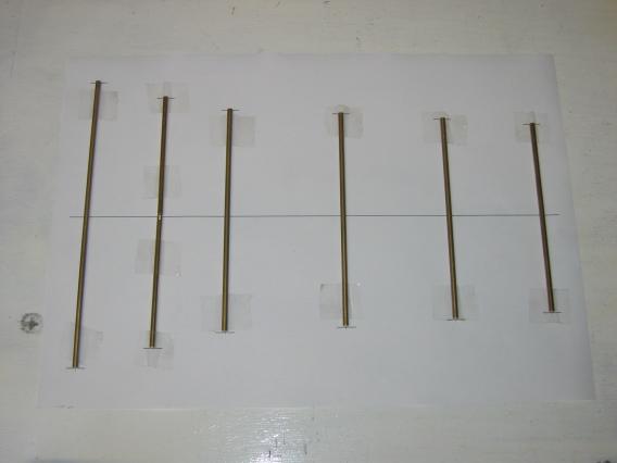
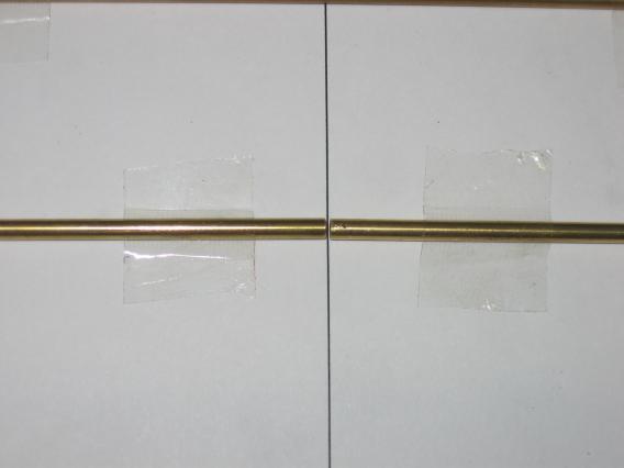
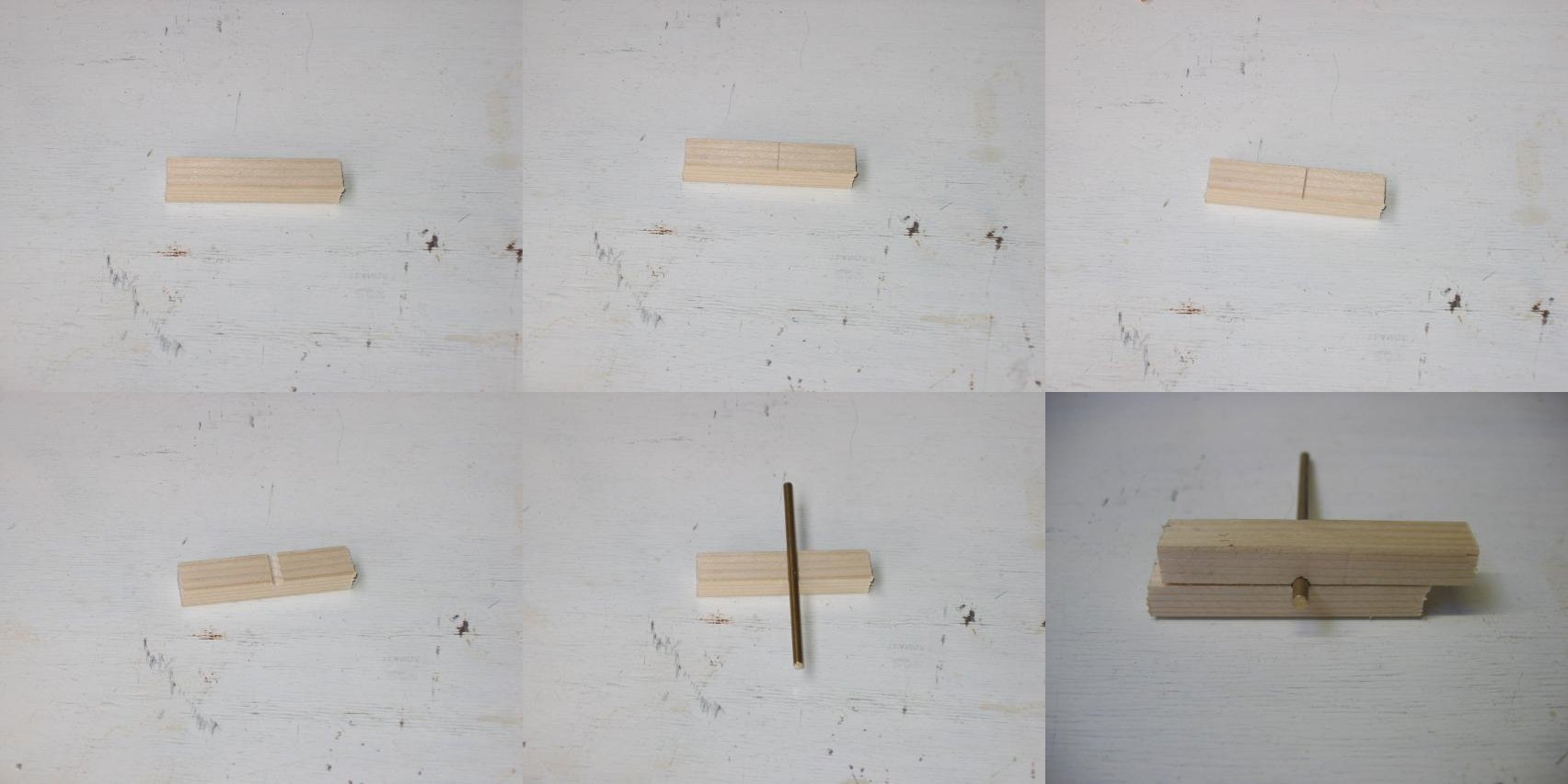
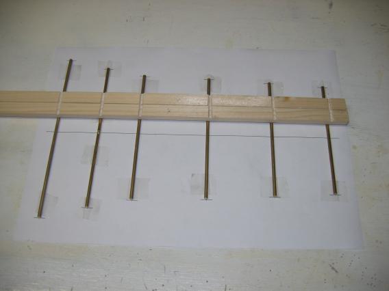
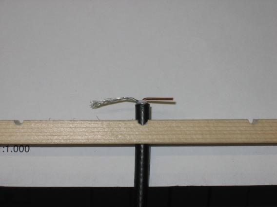
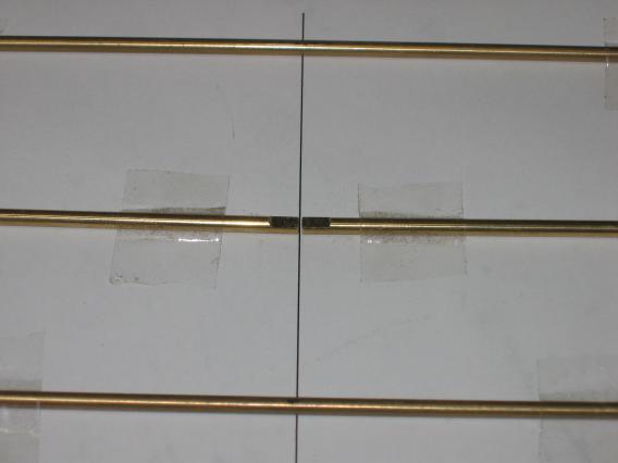
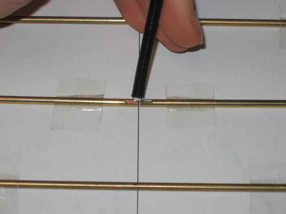
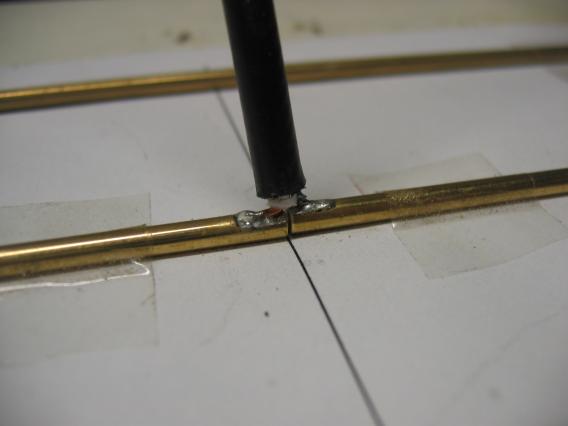
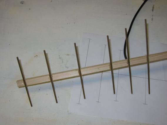
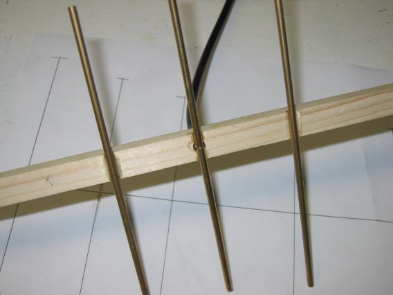
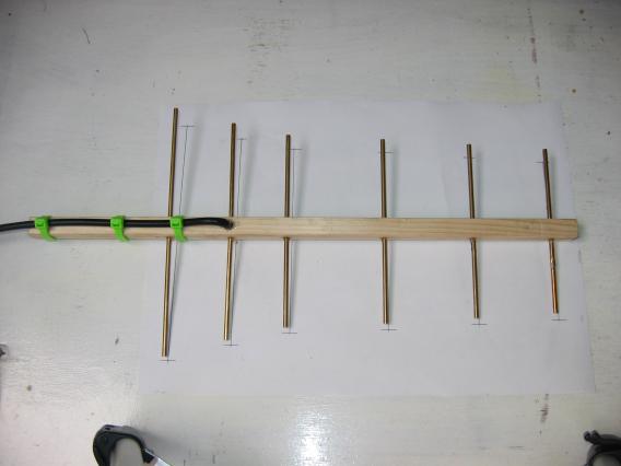
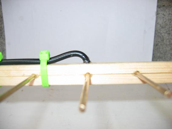
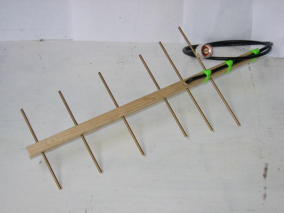
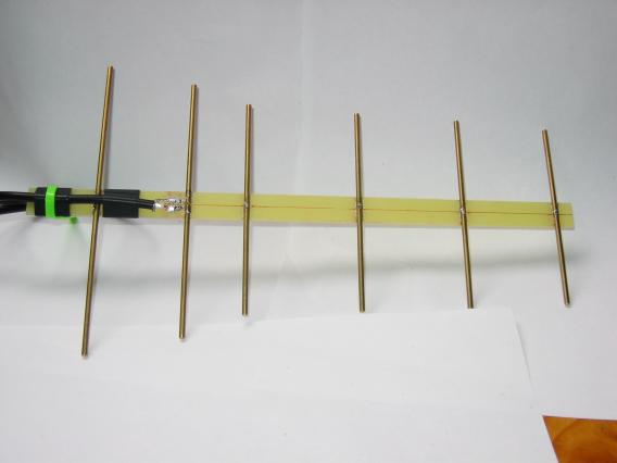
The technique I will show here uses solid brass rods of the elements and a wooden beam made in two half's. The two half's have small recesses which help hold the elements in place, and everything is permanently held together with strong glue.
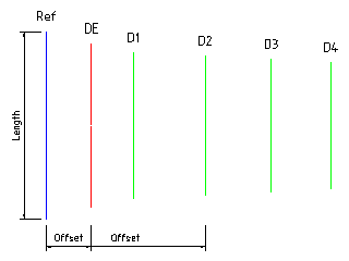
| Element Label | Offset from Ref | Element Length |
|---|---|---|
| Ref | 0 mm | 171 mm |
| DE | 41 mm | 149 mm (2 * 74.5 mm) |
| D1 | 79 mm | 132 mm |
| D2 | 144 mm | 127 mm |
| D3 | 204 mm | 120 mm |
| D4 | 258 mm | 114 mm |

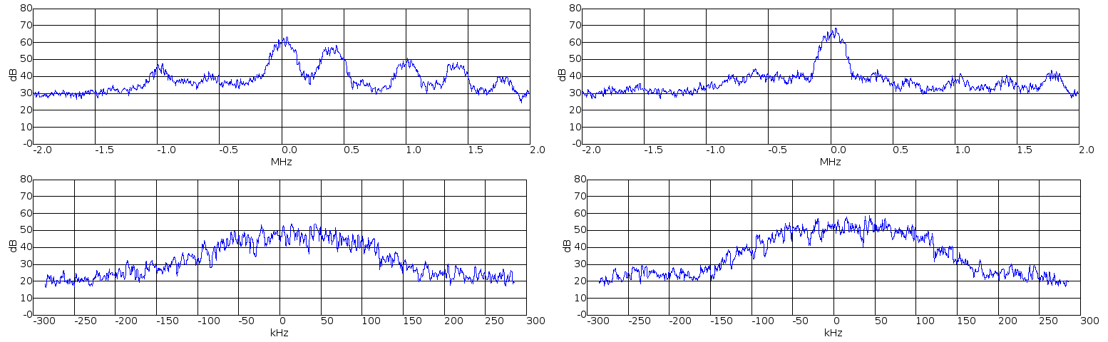
The following image (from a USRP) shows the difference between the monopole antenna and the yagi antenna for a weak BTS signal at 937.8 MHz. The monopole is on the left and the yagi on the right.
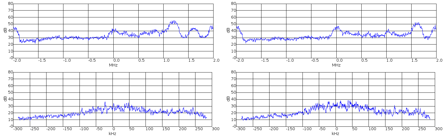
From looking at the image I would suggest that in this test the yagi has between 4 and 6 dB gain over the monopole antenna. I think the main improvement is shown in the directionality. In the upper left a large signal is shown at about 1.2 MHz above the center frequency, in the upper right image this BTS signal is attenuated by about 15 dB. Though the signal at about 1.6 MHz seems to have had an increase in gain with the yagi antenna.
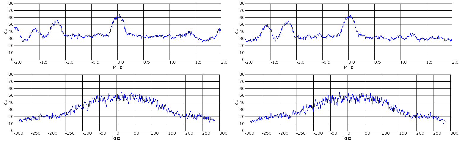
The test in Image ? shows a local strong BTS signal but there is no noticeable improvement in the signal strength.
The test in Image ? shows another BTS with a small improvement in signal gain, but quite a marked improvement with 4 BTS signals being significantly attenuated.
For an absolute gain test you would need a signal generator, field strength meter and an RF shielded environment, which I don't have access to. Another option would be to do a test outside with clear light of sight between the test antenna and the BTS, I might look into this at some point.
Europe, Middle East, Africa and most of Asia
GSM 900 template
GSM 1800 template
Americas
GSM 850 template
GSM 1900 template
All templates should print fine on ISO A4 or US Legal sized paper.
The construction is relatively straight forward requiring only minimal materials and tools. I think this yagi antenna design offers some real advantages over the monopole antenna design or simple wire antenna.