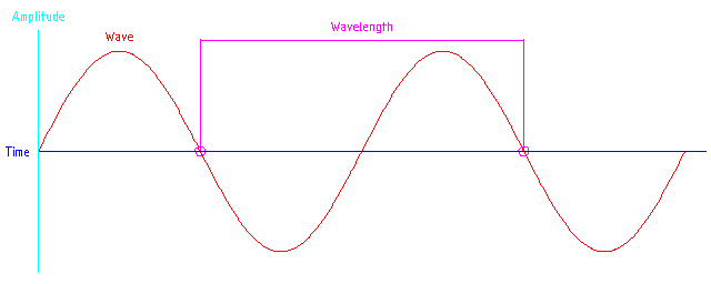
Image 1: Wavelength of a wave.
Using a suitable antenna can greatly improve your chances of success when trying to detect weak radio signals. Unfortunately the range of suitable antennas for the GSM bands are very limited and/or very expensive. Having previously experimented with building homemade/DIY wireless (WiFi) antennas, I felt doing the same for a GSM antenna shouldn't be a problem.
The first port of call was to search on Google for preexisting designs that I would be able to build. Well it turns out that building GSM antennas is not as popular as building wireless antennas. I did find some information on US amateur radio sites about the 33 centimeters (902-928 MHz) band, but nothing around the size I was looking for.
So I had to bite the bullet and design a suitable antenna myself.
The first step in the goal of building an antenna is to set some base requirements for the antenna:
An important measurement in radio is the distance between the same point on two consecutive wave cycles, this distance is known as the wavelength and is denoted with the symbol λ (lambda).
To calculate the wave length of a radio signal we take the Speed of Light in a Vacuum and divide it by the frequency in Hertz (the number of full wave cycles per second).
Wavelength (λ) = Speed of Light / Frequency
The center frequency for my antenna design is 920 MHz so the wavelength is:
Wavelength (λ) = 299792458 / 920000000 = ~0.325861367 = ~0.326 meters
The wavelength for the 920 MHz signal is approximately 0.326 meters. The signals won't be going through a vacuum so a small adjustment needs to be made, we need to reduce the wavelength by about 5%. (I would like to know more about the details about this adjustment value, if you have more information my email address is at the end of the page.) So after the adjustment we have a wavelength of 0.310 meters or 310 millimeters.
There are many different types of antenna, some common types for home construction are a Dipole, Monopole, Yagi-Uda (Yagi), Cantenna (Waveguide) and Parabolic. Image 2 gives an example of what each of the antennas might look like, the red lines are the driven element and the black lines represent wires or surfaces which can direct or reflect the radio signal.
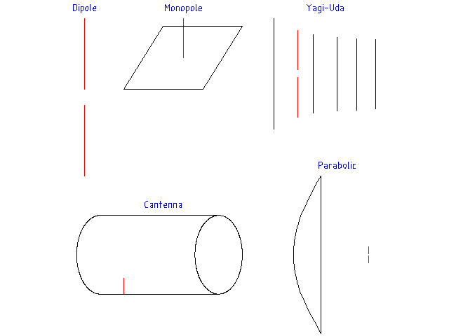
For this project I decided I would build two different types of antenna, a Monopole and a Yagi.
Monopole Design - 1/4 wavelength vertical monopole antenna.
Yagi Design - 6 element yagi antenna.
I've now built and tested the two designs and the results are interesting (at least too me ;).
Testing the monopole design was very surprising in that the roughly cut wire preformed as well as the constructed monopole antenna. I'm guessing that the little improvement in the noise floor was most likely from ground plane acting as a shield to local noise sources.
I'm very happy with the results for the yagi design and I think it fulfils the requirements I set for the antenna. The design seems to work as expected, was easy to build, and seems robust. The only issue with the designs is that I'm not sure of what the actual gain of the antennas are, which is mostly due to the lack equipment/environment to preform accurate testing. The theoretical modeling showed the monopole antenna with a gain of 3 dB and the yagi antenna with a gain of 9 dB, but these models represent an ideal universe and in practice reality doesn't work that way. Thought the yagi's gain of 4 to 6 dB over the monopole is reasonably close to the values shown in the models.
The designs only require a fairly minimal amount of tools and materials, and I tried to be clear and detailed in the descriptions and the photos. Please let me know if anything needs more work or detail.
For the monopole design I will look into using different elements lengths (1/2 wavelength, etc.) to see if they preform any better.
For the yagi design I will trying and design a version with much higher gain, the reason is that the current design seem to have a very wide beam with (about 60 degrees). Trying to pick out a single BTS with a weak signal can be difficult, when there are other strong BTS signals within the beam with. This will be even more important if you where trying to pickup a remote mobile phone.
Another tasks is to test my antenna designs against some commercially designed and built antennas to see how they compare.
If you have any comments or suggestion you can contact me using the email address at the end of the page.