Monopole Design

Back to Designing and building a GSM antenna - Yagi Design

The design

A monopole antenna consists of a 1/4 wavelength vertical element over a solid sheet or radial wire ground plane with diameter of at least 1/4 wavelength. It is a omnidirectional antenna which has the same gain in every direction.

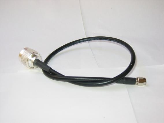
Image 1: Two different styles of monopole antenna (solid sheet and radial wire ground plane).
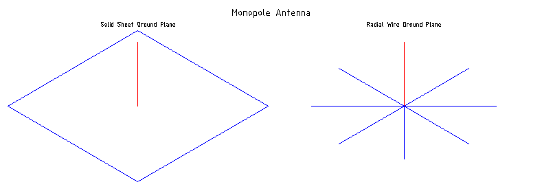
Two different styles of monopole antenna.

I used a version of the Numerical Electromagnetics Code (NEC2) antenna modelling software to help with designing my antenna. In particular I used xnec2c, which is written in C and has graphical user interface written in GTK+.

Image 2: xnec2c screen shot showing different views and information for the GSM-900 monopole antenna.
Screen shot of monopole antenna in xnec2c.

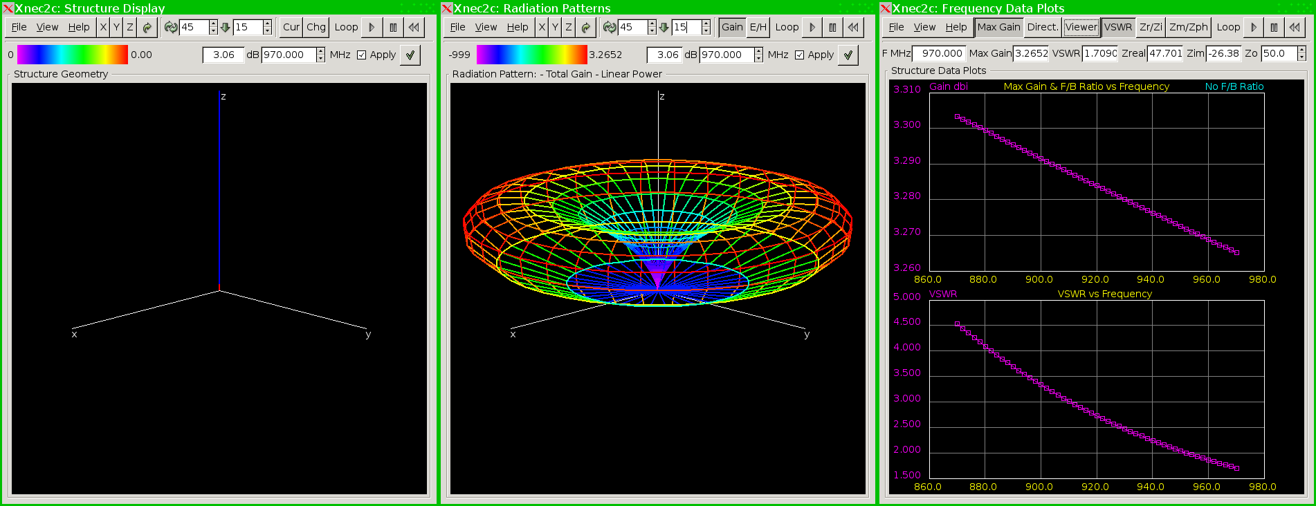
A NEC2 program takes as it's input a text files which can contain very detailed information about a given antenna design. This input is then processed using a number of different algorithms and a text file is produced which contains various low level information about how the signal and antenna have interacted. The output data can then be viewed in a number of different ways that allows the user to evaluate the results.

The input file I used in my design is available at gsm-900_monopole.nec.

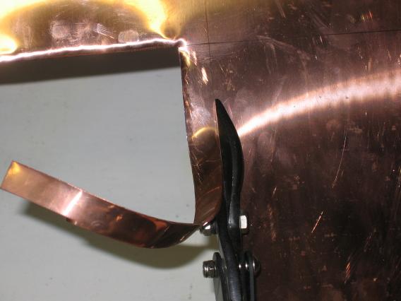
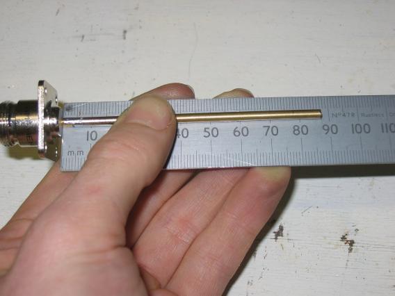
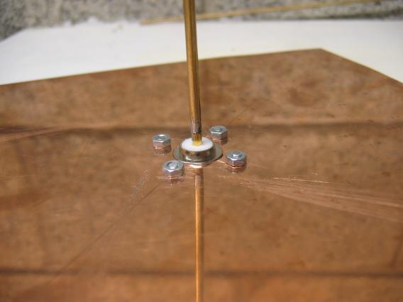
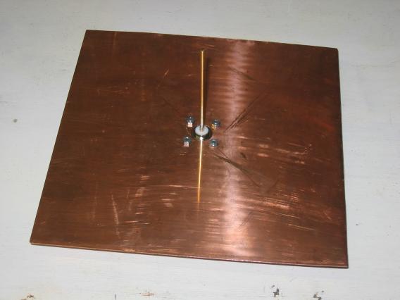
The final GSM-900 monopole antenna design is as follows, a 77.5 mm long 3 mm diameter element coming out of the center of a 200 mm by 200 mm solid metal sheet.

Construction

Materials (Image)
1 @ 3 mm diameter Brass Rod 100 mm in length (thick copper wire would be a suitable alternative)
1 @ 200 mm by 200 mm Copper Sheet (a biscuit tin lid or piece of PCB board would be a suitable alternative)
1 @ N-Type Panel Receptacle Jack (Amphenol Connex Panel Receptacle Jack - Solder Pot Terminal or similar)
4 @ Small Nuts and Bolts (some small washers may also be needed)
Tools (Image)
Hacksaw
Sheet metal shears or jigsaw
Soldering iron and solder
Drill with bits
Selection of hand-file's
Rule and pencil
Suitable screwdriver and/or pliers for nuts and bolts
(I would suggest these as the minimum tools but extra would be helpful such as a vice, etc)
Step 1
Mark and cut the metal sheet to size approximately 200 mm by 200 mm, anything over 160 mm by 160 mm should be fine. Use the file to clean up any sharp edges.
Step 2
Mark the center of the sheet and drill a suitable sized hole so the sheet rests flat on the connector. Place the connector in the hole and use your pencil to mark the center of each of the mounting holes. Drill the holes to a suitable size for your mounting bolts.
Step 3
Using the hand-files shape the end of rod so it fits neatly into the solder cup on the connector. Solder the rod to the solder cup, try and make sure the rod is as straight as possible.
Step 4
Using your ruler and pencil mark a length of 78 mm along the rod, cut just above this mark with your hacksaw. Now using the hand-file carefully file down the the length of the rod until it's length is 77.5 mm.
Step 5
Mount the element connector on the sheet with the nuts and bolts.
Image ?: The finished monopole antenna.
The finished monopole antenna.

Antenna testing

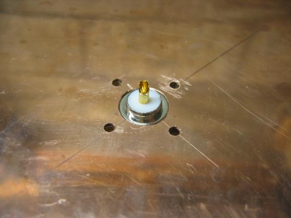
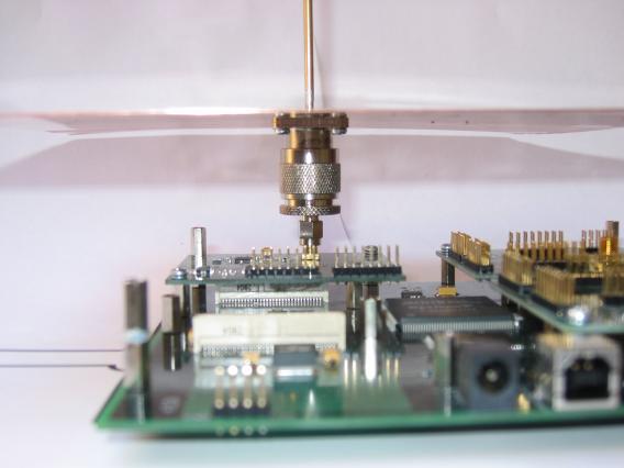
Using Amphenol Connex SMA Plug/N Plug (or pigtail) adapter I carefully mounted the antenna on my USRP (GnuRadio). I then tuned my USRP to the frequency of a strong GSM base stations (see Find a GSM base station manually using a USRP"). Using the usrp_fft.py program and in the averaging mode I took a number of screen shots of each test.

Image ?: USRP 941 MHz 16 decimation, No antenna, Wire antenna, Monopole antenna.
USRP 941 MHz 16 decimation, No antenna, Wire antenna, Monopole antenna.

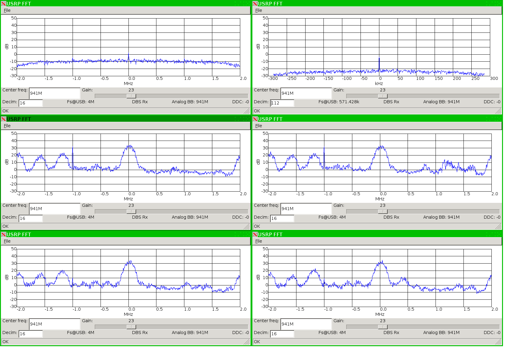
These screen shots show tests with, no antenna, a roughly cut piece of 1/4 wavelength wire, and the monopole antenna. There is only a minimal difference between the piece of wire and the monopole antenna, mostly it's a reduction in the noise value and doesn't effect the signal strength.

Image ?: USRP 941 MHz 112 decimation, Wire antenna, Monopole antenna.
USRP 941 MHz 112 decimation, Wire antenna, Monopole antenna.

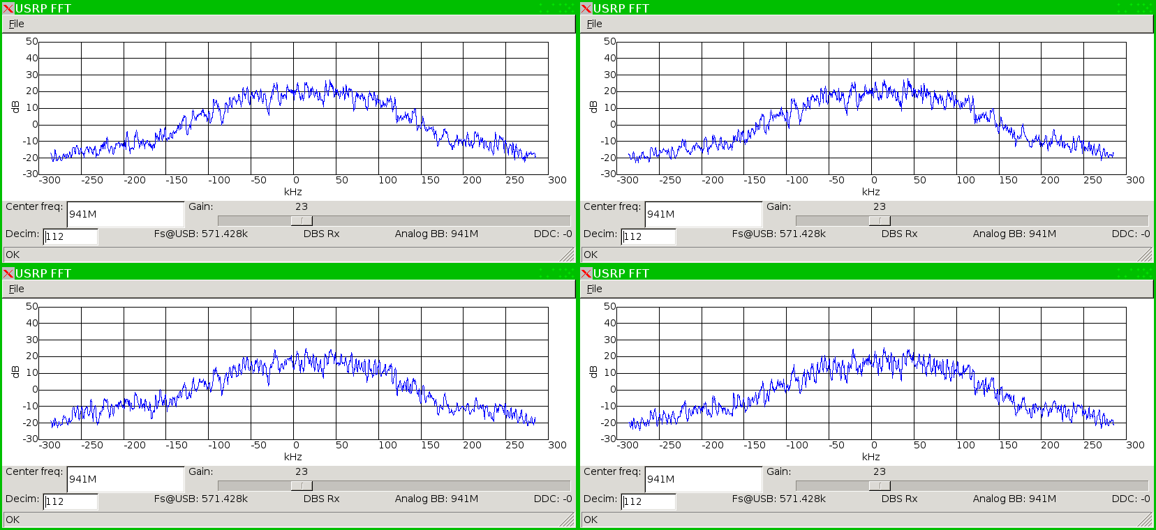
Screen shots of a single GSM channel ~200 kHz, there is also no noticeable difference between between the two screen shots.

Image ?: USRP 947.4 MHz 112 decimation weak signal, Wire antenna, Monopole antenna.
USRP 947.4 MHz 112 decimation weak signal, Wire antenna, Monopole antenna.

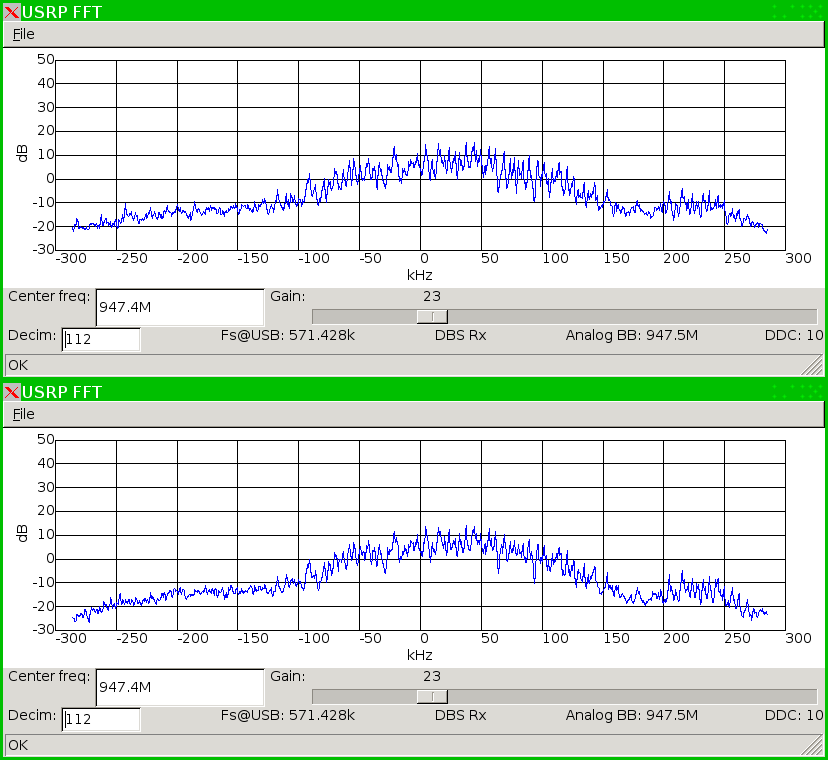
Screen shots of a single GSM channel ~200 kHz from a weaker GSM base station, there is also no noticeable difference between between the two screen shots.

Conclusion

This is very interesting in these tests it seems that there is little or no benefit in building a monopole antenna over using a 1/4 wavelength piece of wire.


Back to Designing and building a GSM antenna - Yagi Design

Last updated 2007-07-22. Copyright © 2007 Robert Fitzsimons. robfitz at 273k dot net